vSphere with Tanzu on VDS with HAProxy
This blogpost is about deploying vSphere with Tanzu on a VDS Setup with HAProxy. I know there has been more than one blogpost written on this topic, but here are the steps I took to get up and running with vSphere with Tanzu. The official VMware [documenatiation] has additional and detailed information.
Pre-requirements
Networking Setup
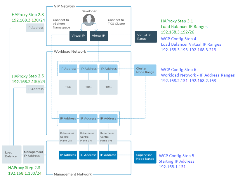
Unify Network with the following VLANs and routable networks:
- VLAN1, subnet 192.168.1.0/24 (in my case this is the native, untagged vlan)
- mask 255.255.255.0, gateway 192.168.1.1, usable IP range 192.168.1.1-192.168.1.254
- VLAN2, subnet 192.168.2.0/24
- mask 255.255.255.0, gateway 192.168.2.1, usable IP range 192.168.2.1-192.168.2.254
- VLAN3, subnet 192.168.3.0/24
- mask 255.255.255.0, gateway 192.168.3.1, usable IP range 192.168.3.1-192.168.3.254
Used versions
- vCenter 7.0U3h (build 20395099)
- ESXi 7.0U3d (build 19482537), single physical server
- HA Proxy 0.2.0
vSphere Setup
vCenter modification to allow single node supervisor control plane VM as written by William Lam (https://williamlam.com/2021/09/single-node-supervisor-control-plane-vm-for-vsphere-with-tanzu-now-possible-in-vsphere-7-0-update-3.html)
- Create (or edit) Cluster
- Enable DRS, Fully Automated, Disable scalable shares
- Enable HA
- Create 3 Distributed Portgroups for above networks
- DPG-VMNet1 – VLAN 1 (or VLAN None in my case) – Management Network – 192.168.1.0/24
- DPG-VMNet2 – VLAN 2 – Workload Network – 192.168.2.0/24
- DPG-VMNet3 – VLAN 3 – Frontend Network – 192.168.3.0/24
- Create 2 Content Libraries
- HA Proxy, download ova file from [here] and add to Content Library
- Tanzu, Subscribed to https://wp-content.vmware.com/v2/latest/lib.json
- Setup / Configure Storage Policies.
- I don’t have vSAN is this environment and created tag based Storage Policies.
Deploy HA Proxy
From Content Library, Select haproxy-v0.2.0 and New VM from this Template
- Step 1: Select Name and folder
- Virtual Machine name: haproxy
- Step 2: Select a compute resource
- Step 3: Review details
- Step 4: License agreements
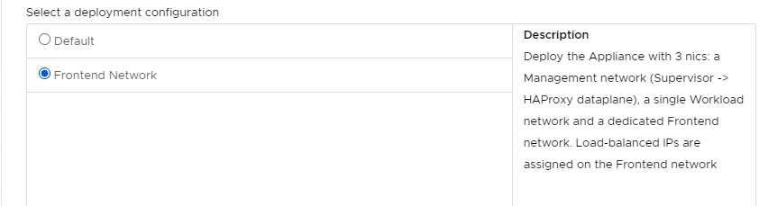
- Step 5: Configuration
- Select: Frontend Network (so 3 networks will be used)
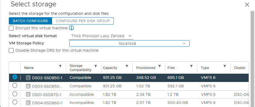
- Step 6: Select Storage
- Select Thin or Thick virtual Disk format
- Select a VM Storage Policy
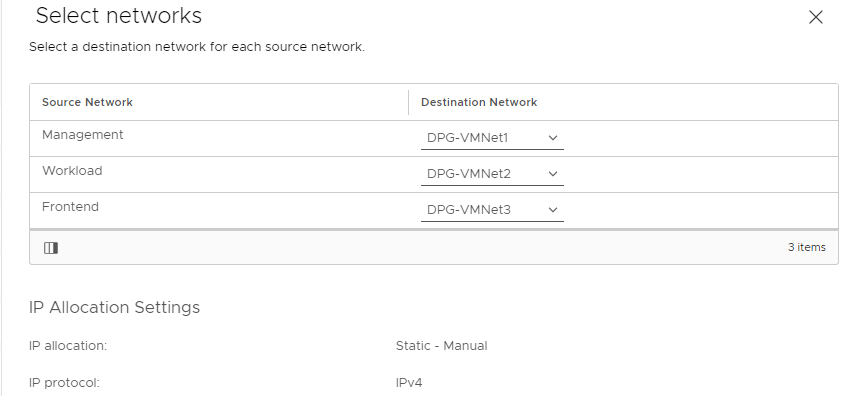
- Step 7: Select Networks
- Step 8: Customize Template
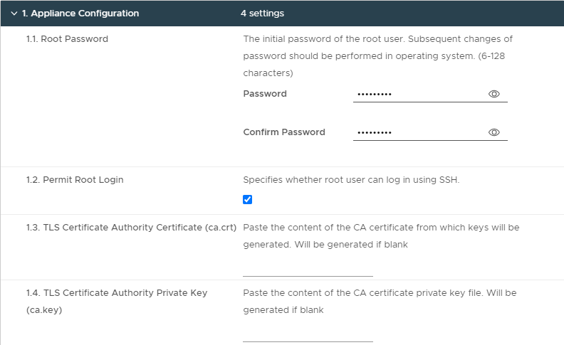
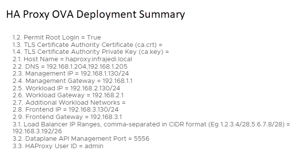
- 8.1 Appliance Configuration
- root password, permit root login, TLS CA Certificate (left blank), TLS CA Private key (left blank)
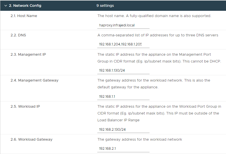
- Step 8.2 Network Config
| Step 8, 2.1 Hostname | haproxy.infrajedi.local | |
| Step 8, 2.2 DNS | 192.168.1.204,192.168.1.205 | |
| Step 8, 2.3 Management IP | 192.168.1.130/24 | Note: the CIDR notation |
| Step 8, 2.4 Management Gateway | 192.168.1.1 | |
| Step 8, 2.5 Workload IP | 192.168.2.130/24 | Note: the CIDR notation |
| Step 8, 2.6 Workload Gateway | 192.168.2.1 | |
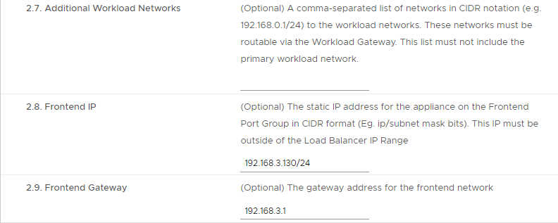
| Step 8, 2.7 Additional Workload Networks | <left blank> | |
| Step 8, 2.8 Frontend IP | 192.168.3.130/24 | Note: the CIDR notation |
| Step 8, 2.9 Frontend Gateway | 192.168.3.1 |
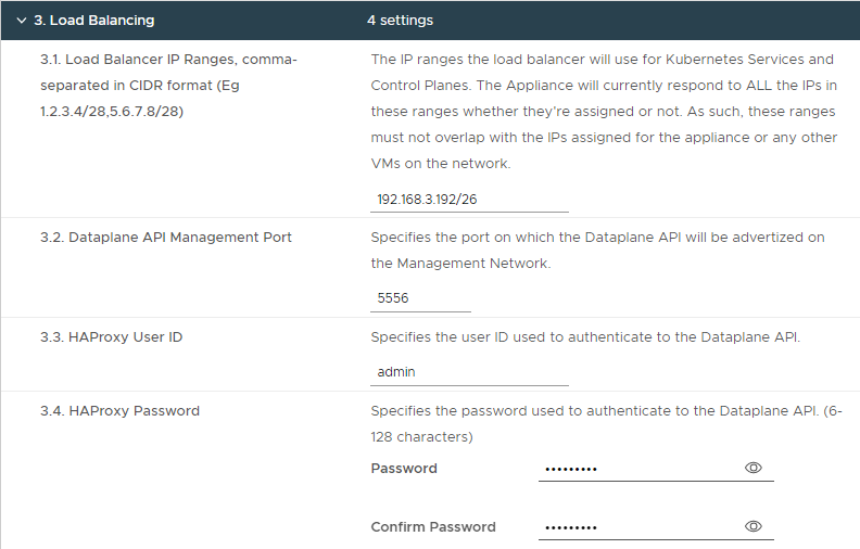
- Step 8.3 – Load Balancing
| Step 8, 3.1 Load Balancer IP Ranges | 192.168.3.192/26 | |
| Step 8, 3.2 Dataplane API Management Port | 5556 | |
| Step 8, 3.3 HAProxy User ID | admin | |
| Step 8, 3.4 HAProxy Password | <password> |
Note: The Load Balancer IP Range is a subset of the 192.168.3.0/24 network and does not contain the Frontend IP as configured in Step 8-2.8. Usable IP Ranges for this /26 subnet are 192.168.3.193-192.168.3.254
Step 9: Summary | Ready to complete
HAProxy VM After deployment
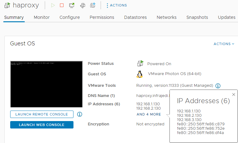
After deployment you should see the 3 IP addresses for Management, Workload and Frontend as configured during deployment.
I had some struggles during earlier deployments related to misconfigured networking. Before you continue with the enablement of Workload Management, have a look at the anyip-routes service with the command systemctl status anyip-routes.service. This service should in active (running) state. I removed the timestamp for visibility of the addition of the route.
● anyip-routes.service
   Loaded: loaded (/etc/systemd/system/anyip-routes.service; enabled; vendor preset: enabled)
   Active: active (running) since Mon 2022-10-24 12:49:25 UTC; 11min ago
  Process: 835 ExecStartPre=/var/lib/vmware/anyiproutectl.sh up (code=exited, status=0/SUCCESS)
  Process: 831 ExecStartPre=/bin/mkdir -p /var/log/vmware (code=exited, status=0/SUCCESS)
 Main PID: 839 (anyiproutectl.s)
    Tasks: 3 (limit: 4708)
   Memory: 560.0K
   CGroup: /system.slice/anyip-routes.service
           ├─839 /bin/bash /var/lib/vmware/anyiproutectl.sh watch
           ├─842 inotifywait -m -e modify /etc/vmware/anyip-routes.cfg
           └─843 /bin/bash /var/lib/vmware/anyiproutectl.sh watch

haproxy.infrajedi.local systemd[1]: Starting anyip-routes.service...
haproxy.infrajedi.local anyiproutectl.sh[835]: adding route for 192.168.3.192/26
haproxy.infrajedi.local systemd[1]: Started anyip-routes.service.
haproxy.infrajedi.local anyiproutectl.sh[839]: watching configuration file for changes
haproxy.infrajedi.local anyiproutectl.sh[839]: Setting up watches.
haproxy.infrajedi.local anyiproutectl.sh[839]: Watches established.
Within the files /etc/vmware/route-tables.cfg and /etc/vmware/anyip-routes.cfg and /etc/haproxy/haproxy.cfg you can see what configuration has been made during ova deployment. See my config files below (some lines with comments are removed)
# Configuration file that contains a line-delimited list of CIDR values
# that define the network ranges used to bind the load balancer's frontends
# to virtual IP addresses.
#
192.168.3.192/26
# Configuration file that contains a line-delimited list of values used to
# create route tables on which default gateways are defined. This enables
# the use of IP policy to ensure traffic to interfaces that do not use the
# default gateway is routed correctly.
#
2,workload,00:50:56:86:75:2e,192.168.2.130/24,192.168.2.1
2,workload,00:50:56:86:75:2e,192.168.2.130/24
3,frontend,00:50:56:86:df:4a,192.168.3.130/24,192.168.3.1
3,frontend,00:50:56:86:df:4a,192.168.3.130/24
To enable workload Management in the next step, you need the certificate which can be copied from the contents of /etc/haproxy/ca.crt on the HAProxy VM.
Enable Workload Management
If all went well with the HAProxy deployment you can now Enable Workload Management.
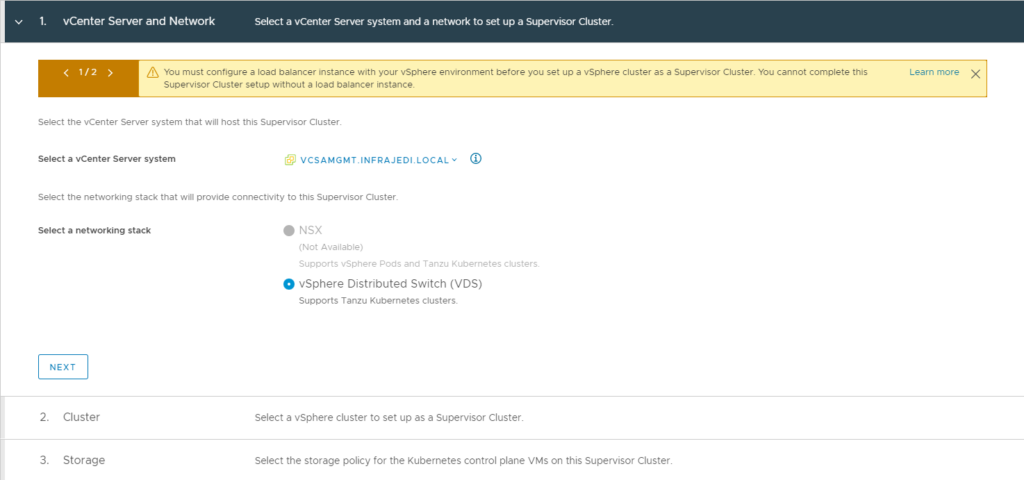
- Step 1: vCenter Server and Network
- Select your vCenter and Select vSphere Distributed Switch (VDS)
- Step 2. Cluster
- Select the cluster as configured earlier
- Step 3. Storage
- Select a storage Policy for your Control Plane VMs
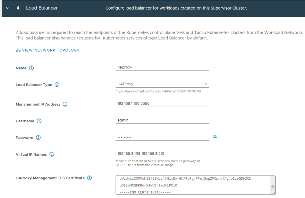
- Step 4. Load Balancer
| Name | haproxy | |
| Load Balancer Type | HAProxy | |
| Management IP Address | 192.168.1.130:5556 | The HA Proxy Management IP address and port as configured in step 8-2.3 and 3.2 during HAProxy deployment. |
| Username | admin | |
| Password | <password> | |
| Virtual IP Ranges | 192.168.3.193-192.168.3.213 | IP range between configured range during HAProxy deployment step 8-3.1: 192.168.3.192/26 I could have used 192.168.3.254 as ending ip address. |
| HA Proxy Management TLS Certificate | <insert> | contents of /etc/haproxy/ca.crt from haproxy vm. |
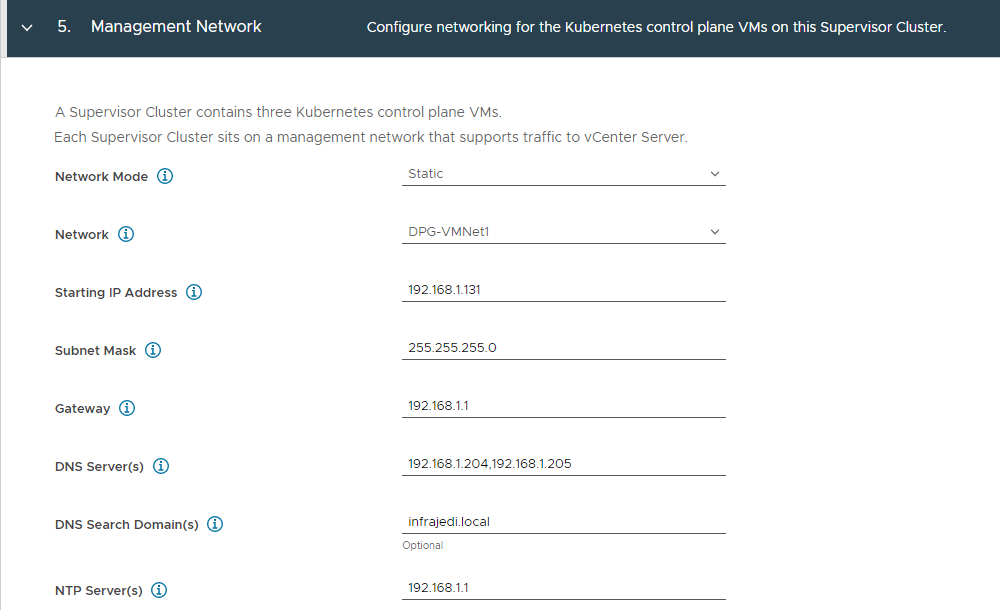
- Step 5: Management Network
| Network Mode | Static | |
| Network | DPG-VMNet1 | The Distributed Portgroup for Management |
| Starting IP Address | 192.168.1.131 | First IP address used in the 192.168.1.0/24 subnet for the worker node management. |
| Subnet Mask | 255.255.255.0 | (equals /24 in cidr notation) |
| Gateway | 192.168.1.1 | |
| DNS Server(s) | 192.168.1.204,192.168.1.205 | |
| DNS Search Domain(s) | Infrajedi.local | |
| NTP Server(s) | 192.168.1.1 |
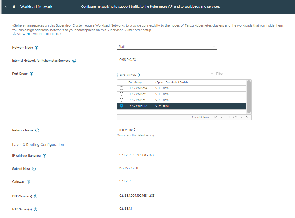
- Step 6: Workload Network
| Network Mode | Static | |
| Internal Network for Kubernetes Services | 10.96.0.0/23 | (= default value) |
| Port Group | DPG-VMNet2 | The Distributed Portgroup for Workload |
| Network Name | dpg-vmnet2 | Automatically filled after selecting Port Group |
| IP Address Range(s) | 192.168.2.131-192.168.2.163 | IP Range used in the 192.168.2.0/24 subnet for the worker nodes. |
| Subnet Mask | 255.255.255.0 | (equals /24 in cidr notation) |
| Gateway | 192.168.2.1 | |
| DNS Server(s) | 192.168.1.204,192.168.1.205 | |
| DNS Search Domain(s) | Infrajedi.local | |
| NTP Server(s) | 192.168.1.1 |
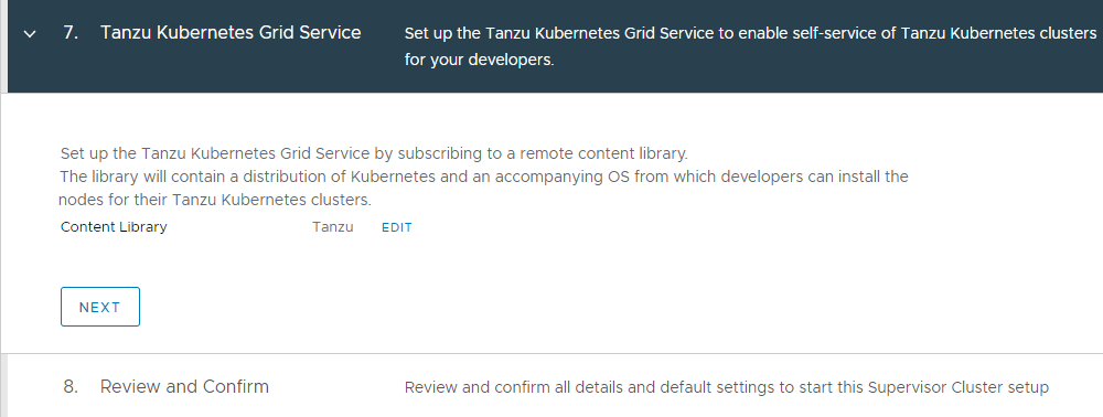
- Step 7: Tanzu Kubernetes Grid Service
- Select the subscribed Content Library containing the Tanzu Images.
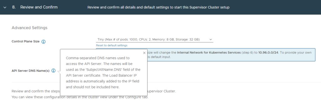
- Step 8. Review and Confirm
- If have selected Tiny for Control Plane Size
- API Server DNS Name(s) left empty.
Depending on your setup, it may take some time to deploy the Supervisor Control Plane VM(s).
After deployment you should see a Supervisor Cluster with a Control Plane node Address listed.
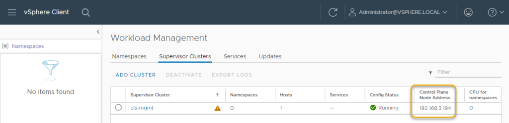
The Warning comes from a license that has not yet been configured.
In the Hosts and Cluster View you will notice a Resource Pool “Namespaces” with a SupervisorControlPlaneVM (1) and more if you did not tweak this setting (default is 3)